Rigidbody Simulation and Fracture
Written before
I finished GAMES103 a few years ago and went through the commonly used rigid bodies, cloths, soft bodies, and fluids in graphics. I was able to get started with physical simulation in graphics, but what about after that? I have to explore the road ahead by myself. I personally prefer the game industry that pursues real-time computing and visual reality (after all, I feel that the current academic community is obsessed with various optimization methods or splicing several methods to write water papers), so I plan to re-examine these basic simulation objects to see if I can go further.
Rigidbody simulation
Impulse
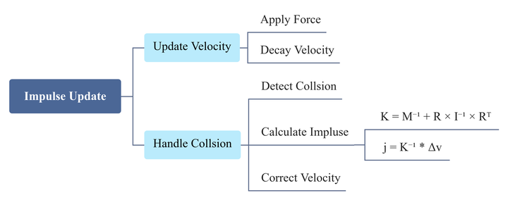
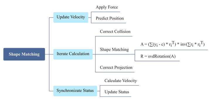
First, let’s warm up a bit by rigid body simulation. For rigid bodies, all game engines generally use linear angular velocity updates and impulses to handle collisions (stability, momentum conservation). The general process is shown in the figure below, and I don’t think I need to elaborate on it.
Shape matching
In comparison, shape matching is rarely used in game engines. Its advantage should be in physics engines (Flex) where different types of objects interact (rigid body, cloth, soft body, mixed fluid). However, considering that the PBD series also follows this idea (free update first, then constrained projection), Just try it out as a rehabilitation exercise. The general idea of shape matching is to first update each vertex freely, and then minimize the mean square error to return it to its original shape (constrained projection).
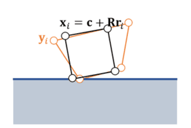
In the algorithm flow, the shape matching part is worth mentioning. First, from the current state of the object, we can get the covariance matrix $S=∑(y_i−c)⋅r_i^T$, and then obtain the optimal transformation matrix $A$ by inverse calculation of the covariance matrix and the pre-calculated reference shape covariance matrix ($Q= ∑r_i⋅r _i^T $). Finally, the optimal transformation matrix $A$ is decomposed by SVD according to $A=U\sum{V}^T$, and the optimal rotation matrix $R=UV^T$ is obtained by removing scaling and shearing on the basis of $A$.
Rigidbody fracture
Industry solutions
Generally speaking, rigid body simulation is not very difficult. If you want to go deeper, you can try rigid body fracture. The application scenario is probably mainly FPS games where destroying terrain can bring greater strategic value. Before starting, let’s collect relevant technical sharing and mature plug-ins to see what the industry is doing now. In the technical sharing, I found GDC2015 Smash Hit’s slice cutting method, GDC2016 Rainbow6’s fixed pattern destruction method, GDC2024 TheFinals’ pre-segmentation impulse threshold separation method, and GDC2025 Epic’s pre-segmentation overlap area separation method. As for mature plug-ins, I found OpenFracture and RayFire for Unity. As for UE, Chaos already includes them natively, which saves a lot of effort.
GDC2015 Smash Hit slice cutting
Smash Hit is a childhood memory for me. Gustafsson’s game design concept for physical playgrounds is popular with me. Sprinkle, Smash Hit, and Teardown are also really cool. For the fracture of Smash Hit, he used a bilateral data structure to explicitly maintain the topological relationship between vertices, edges, and faces; dynamic boundary volume tree plus GJK algorithm for collision detection; and cutting based on vertex side, edge intersection, and closed geometry.
GDC2016 Rainbow6 fixed pattern destruction
In Rainbow Six, Ubisoft Montreal used RealBlast for procedural destruction. Typical objects are broken down into leaf structures for easier destruction.
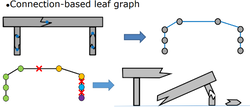
While walls and other surfaces are first projected into two dimensions, then a specific shape is generated based on the input and material parameters, and finally polygon cutting and triangulation are performed.
PS: The second half of the sharing is all about network synchronization and optimization. If you are interested, you can check it out.
GDC2024 TheFinals impulse threshold separation & GDC2025 Epic overlap area separation
These two are put together because they both start from pre-segmented meshes, but in terms of separation logic, the former uses impulse thresholds, while the latter uses overlapped areas (one from stress and one from strain, quite symmetrical, plus I haven’t found a diagram that can well describe the relevant methods). To expand a little, the former uses Niagara’s Mesh Renderer and custom UV sets, adds animation inside the material, and then achieves dynamic fragmentation by setting impulse thresholds; the latter uses strain evaluation and anchoring to achieve dynamic fragmentation by comparing the overlap between the collision shape and the pre-segmented map.
Unity plugins and UE Chaos
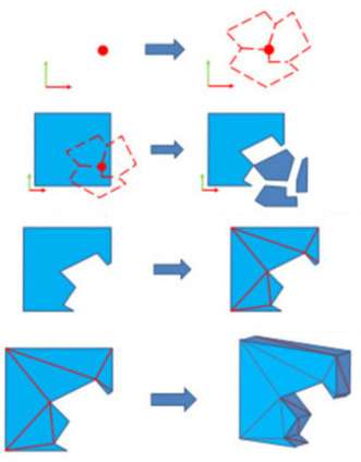
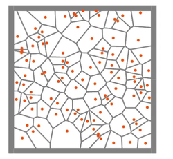
(Detected same frame, automatically merged) In general, the two engines basically only have random face cutting for real-time cutting, while the pre-processing options are much richer, but most of the principles are still Voronoi diagrams. The general concept is to generate a set of points, and then assign a certain area to each point through a series of operations such as triangulation. UE’s uniform fragmentation, cluster fragmentation, and radiation fragmentation are all based on Voronoi diagrams, but the logic of generating points is different.
Custom simulation
After looking at the solutions in the industry, it’s time to come up with some solutions of my own. I personally like the real-time cutting and fracture effect of Smash Hit, but looking at all the methods, except for this and the wall solution of Rainbow Six RealBlast, the other cutting is random/preset and has nothing to do with collision information. Rainbow Six’s “generating a specific shape from input and material parameters” step directly discourages me, so I’ll start with the relevant methods of Smash Hit.
Data structure
The bilateral data structure used by Gustafsson explicitly maintains the topological relationship between vertices, edges, and triagles. Points are easy to understand, and edges and triagles are because each cut will open new points on the edge and cut new surface. The bilateral structure is still a bit complicated. Maybe Gustafsson cuts based on vclosed geometry, so this is needed. However, if the cutting logic is triangulation and used vertex deduplication, the stored mesh structure will be relatively simple.
1 | struct MeshVertex{ float3 position, normal; float2 uv; } |
Fracture method
As mentioned in the previous data structure, the project uses triangulation to simplify cutting. The general process is as follows:
Vertex side division: divide the vertices into two groups above the cutting plane (topSlice) and below (bottomSlice).
Edge intersection calculation: for the cut edges, interpolate and calculate the intersection, generate the cutting surface vertices and add them to the cutting surface point set (cutVertices).
Triangulation: triangulation point set (cutVertices) and constraint edges (constraints).
Vertex deduplication: merge duplicate cutting surface vertices (WeldCutFaceVertices) to eliminate redundant vertices.
The most difficult part is triangulation, which is implemented using Delaunay triangulation with bin sorting and point-by-point insertion. The project has hundreds of lines, which is not suitable for posting all of them. Here is a brief introduction to the basic process.
1 | // Input: Vertex list, Constrained edge list Output: Triangle index list |
Handle collision
Finally, it is the collision response part that need some skills and inspirations. Random collision frature just cuts a surface at a random position and angle each time, and the physics depends on the speed distribution afterwards. After some trouble, I came up with three physical approximation tricks, which can be regarded as a bit innovative. The first is that the faster the collision speed, the smaller the fragments, the higher the corresponding impact strength, and the more thorough the material crushing. The second is that the closer the collision point is to the edge, the easier it is to half-cut, corresponding to the local cracking of the edge brittle fracture. The third is to cut the surface inward at a random angle, corresponding to the simulated stress inward rupture along the maximum shear direction.
The general approach is to first determine whether it is a full cut or a half cut based on the distance from the collision point to the center and the edge, then project the mesh vertices to the plane perpendicular to the collision speed, construct the initial cut line with the collision projection point and the random angle, then find the point farthest from the line from all mesh projection points, and move the initial cut line to this point according to the cutting ratio. Then apply the inward angle to complete the cutting line information in the world space (to handle the scaling of the object) to obtain the cutting surface. It is not that complicated to describe, but I still encountered many pitfalls in practice (for example, the initial rough cutting was to scale the axisymmetric rectangle into a square and then cut two points on the edge of the unit inscribed circle according to the area ratio, and the fine cutting used the two-dimensional convex hull to calculate the area ratio. Also, I was misled by the Unity function for a long time when dealing with inclination. The solution was obtained by recalling left-multiplying the normal by the transposed inverse matrix during rendering). I don’t know if I can use it to cope with master’s thesis.
1 | // Asynchronous process in the main code |
Result showcase
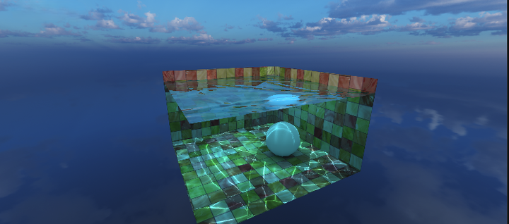
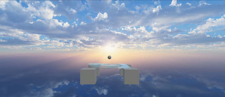
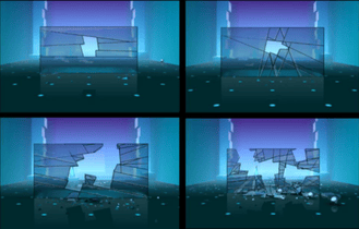
Here, I demonstrate the situation where the ball hits the middle and edge of the glass to show the full cut and half cut. The scene is very rough and is only for technical demonstration. It is the deepest attempt in my personal technology. I may try to include it in my portfolio after I imitate a Smash Hit scene.

Update: Slightly improved when imitating the Smash Hit, optimized the handling of continuous collisions
 wechat
 alipay