Water Caustics Rendering and Simulation
Written before
When I was an undergraduate, I saw Evan’s WebGL_Water and collected it. Now I came across the final graphics assignment in a graduate course. Looks like it has good performance, so I modified it to an Unity version and ran it on my phone. I will briefly talk about the main points of the project in two parts: simulation and rendering.
Simulation
The simulation part simply uses local averaging and differentiation, which can also be seen as a very simplified version of the shallow water wave equation, taking four neighboring points to calculate the height difference and then diffusing. Water waves (and subsequent caustics) are represented by textures, where the r channel of the water wave texture is the height field and the g channel is the velocity field.
1 | float average = ( |
Then there is ripple smoothing and volume preservation. The definite integral is thrown to GPT to calculate, freeing up the brain
1 | float drop = max(0, 1.0 - length(float2(0.5, 0.5) - coord) / 0.5); |
Rendering
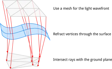
Generally speaking, path tracing is used for caustics, but path tracing is not specific to caustics. It is a general solution for simulating light behavior and rendering realistic images. Path tracing is indeed very powerful, but it is still too hardware-intensive. Regardless of static water (that is too boring), there are also methods for dynamic water that use meshes to approximate the light wavefront and other screen-space-based methods. Both are very economical, but the light wavefront mesh is more intuitive and physical, so it is used in this project. Each vertex of the mesh represents a beam of light that leaves the light source and falls somewhere in the scene. Each triangle of the mesh approximates all possible light rays between the triangle vertices. An increase in the area of the triangle means that the light spreads out and the intensity becomes dimmer. A decrease in area means that the light is focused and should be brighter. In summary, the change in brightness is proportional to the change in area. Directly representing the area instead of sampling avoids the need for a large number of samples to confirm the caustic shape, so it is more efficient. It should be noted that this method is not a panacea, but it is suitable here because light is refracted through a flat body of water.
Then the question arises again, how to access all three vertices in a triangle, geometry shader? It is indeed a solution, but it is too complicated and I am too lazy to write it. It happens that the fragment shader retains the partial derivative change rate in order to calculate the LOD. Here is a summary:
Fragment shaders have an interesting evaluation strategy: they are always evaluated 4 at a time in 2x2 groups. Since all fragment shaders in the group share the same instruction pointer, each fragment shader can compute the instantaneous screen-space partial derivatives for any value along the x and y axes using the finite differences between itself and the neighboring fragment shaders along that axis. This is often used to compute texture mipmap levels.
1 | v2f vert (appdata v) //pass vertex info |
Written Behind
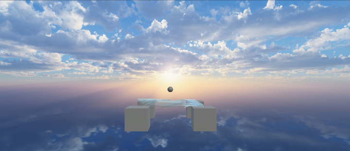
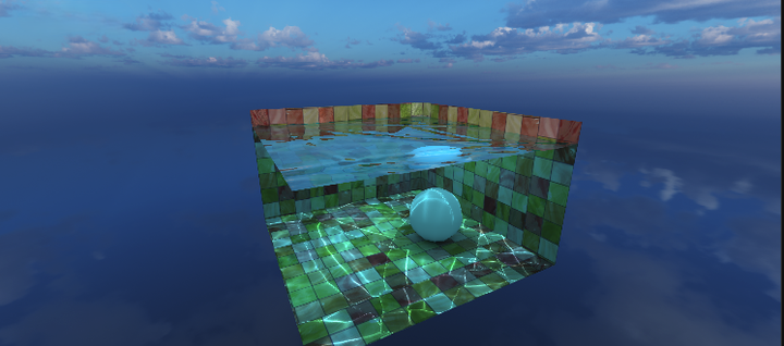
Finally, I added a lot of details and the corresponding control scripts to complete the demo. Compared with the original version, I added a skybox and normal map, which is probably more suitable for general scenes. It can be further expanded to any underwater model, but that would just be a ray tracing acceleration structure, which doesn’t seem very interesting. I ran it on my phone and computer, and it’s done.
| Redmi K20 | Redmi K50 | Laptap(GTX 1650) | |
|---|---|---|---|
| FPS | 60 | 121 | 810 |
 wechat
 alipay